
The multimeter offers two resistance measurements: 2-wire and 4-wire ohms. For both methods, the test current flows from the input HI terminal, through the resistor being measured. For 2-wire ohms, the voltage drop across the resistor being measured is sensed internal to the multimeter. Therefore, test lead resistance is also measured. For 4-wire ohms, separate "sense" connections are required. Because no current flows in the sense leads, the resistance in these leads does not give a measurement error.
|
|
The errors mentioned earlier in this chapter for DC voltage measurements also apply to resistance measurements. Additional error sources unique to resistance measurements are discussed below. |
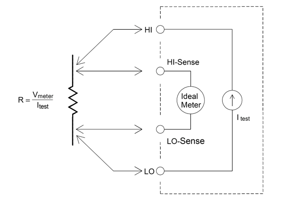
The 4-wire ohms method provides the most accurate way to measure small resistances because it reduces test lead and contact resistances. This is often used in automated test applications where resistive and/or long cable, numerous connections, or switches exist between the multimeter and the DUT. The recommended connections for 4-wire ohms measurements are shown below.
For the 34465A and 34470A, you can also enable offset compensated resistance measurements using [SENSe:]{RESistance|FRESistance}:OCOMpensated {OFF|ON}. Offset compensation removes the effects of small dc voltages in the circuit being measured. The technique involves taking the difference between two resistance measurements, one with the current source set to the normal value, and one with the current source set to a lower value.
To eliminate offset errors associated with test lead resistance in 2-wire ohms measurements, follow these steps:
Short the test lead ends together and read the displayed test lead resistance.
Press Null. The multimeter will store the test lead resistance as the 2-wire ohms null value, and subtract that value from subsequent measurements.
See also "Null Measurements."
When measuring resistors designed for temperature measurements (or other resistive devices with large temperature coefficients), be aware that the multimeter will dissipate some power in the DUT. The following table shows several examples.
| Range | Standard Test Current | Power Dissipation in DUT |
|---|---|---|
| 1 GΩ | 500 nA | 2.5 µW |
| 100 MΩ | 500 nA | 2.5 µW |
| 10 MΩ | 500 nA | 2.5 µW |
| 1 MΩ | 5 µA | 25 µW |
| 100 kΩ | 10 µA | 10 µW |
| 10 kΩ | 100 µA | 100 µW |
| 1 kΩ | 1 mA | 1 mW |
| 100 Ω | 1 mA | 100 µW |
If power dissipation is a problem, you should select a higher fixed range (all multimeter models) or, for the 34465A/70A, select the low power resistance measurement mode (see Resistance (front panel), or [SENSe:]{RESistance|FRESistance}:POWer:LIMit[:STATe] (remote). The low power mode sources less test current per measurement range than is normally sourced for standard resistance measurements, to reduce power dissipation and self-heating in the DUT. The following table shows the various resistance ranges, the standard test current delivered for 2- and 4-wire resistance measurements, and the low power mode test current.
| Range | Standard Test Current | Low Power Mode Test Current |
|---|---|---|
| 1 GΩ | 500 nA | 500 nA |
| 100 MΩ | 500 nA | 500 nA |
| 10 MΩ | 500 nA | 500 nA |
| 1 MΩ | 5 µA | 5 µA |
| 100 kΩ | 10 µA | 5 µA |
| 10 kΩ | 100 µA | 10 µA |
| 1 kΩ | 1 mA | 100 µA |
| 100 Ω | 1 mA | 100 µA |
When you are measuring large resistances, significant errors can occur due to insulation resistance and surface cleanliness. You should take the necessary precautions to maintain a "clean" high–resistance system. Test leads and fixtures are susceptible to leakage due to moisture absorption in insulating materials and "dirty" surface films. Nylon and PVC are relatively poor insulators (109 Ω) when compared to PTFE insulators (1013 Ω). Leakage from nylon or PVC insulators can easily contribute a 0.1% error when measuring a 1 MΩ resistance in humid conditions.